Feedback control involves adjusting a manipulated variable (m) in response to a deviation or error (e) between the controlled variable (c) and its desired set point (r) to reduce or eliminate the error. However, feedback control is reactive and cannot prevent errors from occurring as it can only take corrective action after an error has already developed. Furthermore, due to delays and lags in the response of the controlled variable to manipulation, the correction may take some time to take effect, during which the deviation may initially worsen before eventually improving. As a result, the effectiveness of feedback control is limited by the responsiveness of the process to manipulation.
In contrast, feedforward correction can proactively compensate for any changes in the load variable as soon as they enter the process. If the feedforward model is accurate and the load dynamics are favorable, the effects of the load change can be nullified before they affect the controlled variable. However, since feedforward models and sensors are not perfect, feedforward loops may require feedback trimming to correct any errors.
Feedback Control
The goal of a process control system is to maintain the controlled variable at a desired set point despite any disturbances that may arise. The control system achieves this by adjusting one or more manipulated variables to counteract any variations in the load(s). To ensure that the controlled variable remains stable, the process must be in a balanced state.
Feedback control is used to regulate the process by responding to any changes in the controlled variable that are caused by variations in the load. Any deviations in the controlled variable are translated into changes in the manipulated variable, which are then sent back to the process to restore equilibrium.
Figure 1.1a illustrates how information flows from the process output back to its manipulated input in a feedback control system. The load variable, denoted as ![]() , refers to the flow of mass or energy that enters or exits the process and must be balanced by an equal flow. The load variable may have multiple components, such as temperature and flow in a temperature loop, but can be controlled by a single manipulated variable, such as steam flow. The steady state gain, denoted as
, refers to the flow of mass or energy that enters or exits the process and must be balanced by an equal flow. The load variable may have multiple components, such as temperature and flow in a temperature loop, but can be controlled by a single manipulated variable, such as steam flow. The steady state gain, denoted as ![]() , and dynamic gain vector, denoted as
, and dynamic gain vector, denoted as ![]() , can differ between the manipulated and load variables, indicated by their respective subscripts,
, can differ between the manipulated and load variables, indicated by their respective subscripts, ![]() and
and ![]() .
.
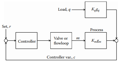
Figure 1.1a [Load changes can enter through different gain and dynamics from the controller output].
Limitations of Feedback Control
Due to inherent delays in the response of a controlled variable to changes in a manipulated variable, feedback control cannot immediately correct a deviation when it is detected. As a result, a deviation in the controlled variable must occur before corrective action can be initiated. Achieving perfect control is not possible, even in theory, because of this fundamental limitation. The feedback controller must use trial and error to determine the optimal value for the manipulated variable to balance the load, while monitoring the impact of its output on the controlled variable.
Best-Possible Feedback Control
The presence of deadtime in a feedback control loop places an absolute constraint on its performance. In Figure 1.1b, a step-load change is applied to a process that consists of deadtime and a single lag in both the load path (![]() ) and the manipulated-variable path (
) and the manipulated-variable path (![]() ). The time scale is given in units of deadtime (
). The time scale is given in units of deadtime (![]() ) in the path of the manipulated variable. To make the illustration more straightforward, both paths have identical deadtimes, although any deadtime in the load path, or its absence, would produce the same response with a shift in time. Furthermore, the steady-state gains in both paths are assumed to be equal for simplicity.
) in the path of the manipulated variable. To make the illustration more straightforward, both paths have identical deadtimes, although any deadtime in the load path, or its absence, would produce the same response with a shift in time. Furthermore, the steady-state gains in both paths are assumed to be equal for simplicity.
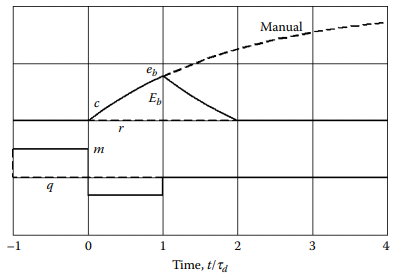
Figure 1.1b [The best-possible load response for a process having deadtime and a single lag].
At time –1, a step decrease in load q enters the process.
After the deadtime in the load path expires, at time zero, the controlled variable ![]() responds, beginning to rise along an exponential curve determined by the gain and lag in the load path.
responds, beginning to rise along an exponential curve determined by the gain and lag in the load path.
If the controller were left in Manual, it would continue to a new steady state. In this example, ![]() is 2.0, leaving the final value of
is 2.0, leaving the final value of ![]() in Manual having changed twice as much as load
in Manual having changed twice as much as load ![]() ; the time constant
; the time constant ![]() of the load lag in this example is 2.0
of the load lag in this example is 2.0 ![]() . Also shown is the possible return trajectory of c to set point
. Also shown is the possible return trajectory of c to set point ![]() if the manipulated variable m were to step as soon as any deviation is detected, i.e., at time zero, by an amount
if the manipulated variable m were to step as soon as any deviation is detected, i.e., at time zero, by an amount
(1) ![]()
where ![]() is the exponential operator 2.718. This move turns out to be the best that is possible by a feedback controller, as it causes the deviation to decay to zero during the next deadtime. The peak deviation reached during this excursion is
is the exponential operator 2.718. This move turns out to be the best that is possible by a feedback controller, as it causes the deviation to decay to zero during the next deadtime. The peak deviation reached during this excursion is
(2) ![]()
At the time the peak is reached, the controller output must be stepped to match the new steady-state load. The leading edge of the curve, i.e., up to time 1.0, is determined completely by the load step and the gain and dynamics in its path; the trailing edge is determined by the controller and its tuning.
The leading and trailing edges of the best response are complementary, so that the area that they enclose is
(3) ![]()
These values of ![]() and
and ![]() are the best that can be obtained for any feedback controller on a process whose dynamics consist of deadtime and a single lag. A real controller will yield a somewhat larger peak deviation and an area at least twice as great, depending on its modes and their tuning. If the process contains two or more lags, the value of
are the best that can be obtained for any feedback controller on a process whose dynamics consist of deadtime and a single lag. A real controller will yield a somewhat larger peak deviation and an area at least twice as great, depending on its modes and their tuning. If the process contains two or more lags, the value of ![]() remains the same as estimated above but is more difficult to approach with a real controller.
remains the same as estimated above but is more difficult to approach with a real controller.
Integrated Error
The actual effectiveness of feedback control depends on the dynamic gain of the controller, which is a function of its control modes and their tuning. Although a high controller gain is desirable, the dynamic gain of the closed loop at its period of oscillation must be less than unity if the loop is to remain stable. In effect, then, the dynamic gain of the process dictates the allowable dynamic gain of the controller.
For each process and controller, optimum settings exist that minimize some objective function such as Integrated Absolute Error (IAE). However, most controllers are not tuned optimally, for various reasons, such as process nonlinearities. Therefore, controller performance needs to be stated in terms of the actual settings being used.
As an example, the integrated error produced by a load change to a process under ideal Proportional Integral-Derivative (PID) control will be evaluated based only on its mode settings. The controller output ![]() at time
at time ![]() is related to the deviation
is related to the deviation ![]() between the controlled variable and its set point by
between the controlled variable and its set point by
(4) ![]()
where ![]() ,
, ![]() and
and ![]() are the percent Proportional Band, Integral time and Derivative time, respectively, and
are the percent Proportional Band, Integral time and Derivative time, respectively, and ![]() is the output of the controller at time,
is the output of the controller at time, ![]() when it was first placed in Automatic. Let
when it was first placed in Automatic. Let ![]() be a steady state, so that
be a steady state, so that ![]() =0 and its derivative is also zero.
=0 and its derivative is also zero.
Then a load change arises, causing the controller to change its output to return the deviation to zero. When a new steady state is reached, the controller will have an output ![]() :
:
(5) ![]()
where ![]() and its derivative are again zero.
and its derivative are again zero.
The difference in output values between the two steady states is
(6) ![]()
Solving for the integrated error:
(7) ![]()
For any sustained load change, there must be a corresponding change in the controller output, and in fact the current load is often reported as the steady-state controller output. The wider the proportional band and the longer the integral time, the greater will be the integrated error per unit load change. Therefore, loops with controllers having large PI products are candidates for feedforward control.
Feedforward Control
The use of feedforward control provides a more direct approach to maintaining control of a process, as it avoids the need to find the correct manipulated variable value by trial and error, which is characteristic of feedback control. In a feedforward control system, a model that incorporates the primary components of the load is used to calculate the necessary value of the manipulated variable required to maintain control at the set point.
Information flows forward in a feedforward system, as illustrated in Figure 1.1c, from the load to the manipulated variable input of the process. The set point provides the system with a command. (Note that if the controlled variable is used in the calculation instead of the set point, a positive feedback loop would be created.)
A feedforward system typically employs a system, rather than a single control device, since it is not always practical to provide the necessary computing functions with a single device or function. Instead, a feedforward system usually comprises several hardware devices or software blocks that implement a mathematical model of the process.
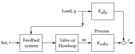
Figure 1.1c [Feedforward calculates the value of the manipulated variable based on current load and set point].
Load Balancing
To maintain the controlled variable at the set point, a dynamic balance must be achieved. This balance is established by continuously solving the material and/or energy balance equations of the process. Upon detecting a load change, the manipulated variable is automatically adjusted to maintain balance. Although perfect control is theoretically possible, it is difficult to achieve in practice due to the inability to exactly replicate the process balance.
The material and energy balance equations are usually easy to write for a given process. Nonstationary parameters such as heat-transfer and mass-transfer coefficients typically have little effect on the performance of a feedforward system. The primary components of load are usually inflow or outflow when controlling level or pressure, feed flow and feed composition when controlling product composition, and feed flow and temperature when controlling product temperature. Flow is the primary component in most applications because it can change rapidly and widely.
Secondary load components like composition and temperature are less likely to exhibit wide excursions, and their rate of change is usually limited by upstream capacity. Feedforward systems generally omit these components and rely on feedback control to accommodate their effects.
The output of a feedforward system should ideally be an accurately controlled flow rate, but this cannot usually be achieved by directly manipulating the control valve due to valve nonlinearities and external factors like upstream and downstream pressure variations. Therefore, most feedforward systems rely on flow measurement and feedback control to achieve accurate flow rate manipulation. Only when the range of the manipulated variable exceeds that of the flowmeter or the required speed of response exceeds that of a flow loop should direct valve positioning be considered, and in such cases, obtaining a reproducible response is crucial.
Steady-State Model
The first step in designing a feedforward control system is to form a steady-state mathematical model of the process. The model equations are solved for the manipulated variable, which is to be the output of the system. Then the set point is substituted for the controlled variable in the model.
This process will be demonstrated by using the example of temperature control in a heat exchanger (Figure 1.1d).
A liquid flowing at rate W is to be heated from temperature ![]() to controlled temperature
to controlled temperature ![]() by steam flowing at rate
by steam flowing at rate ![]() .
.
The energy balance, excluding any losses, is
(8) ![]()
Coefficient ![]() is the heat capacity of the liquid and
is the heat capacity of the liquid and ![]() is the latent heat given up by the steam in condensing. Solving for
is the latent heat given up by the steam in condensing. Solving for ![]() yields
yields
(9) ![]()
where ![]() , set point
, set point ![]() replaces
replaces ![]() , and
, and ![]() and
and ![]() are load components to which the control system must respond.
are load components to which the control system must respond.
Note that this energy balance is imperfect, because it disregards minor loads such as the heat losses to the environment and any variations in the enthalpy of the steam.
Another factor is that even the two major loads cannot be measured perfectly, as there are no error-free sensors of flow and temperature. The net result is a model that is approximately an energy balance around this process.
An implementation of
(10) ![]()
is given in Figure 1.1d. A control station introduces ![]() into the difference lock [
into the difference lock [![]() ] where input
] where input ![]() is subtracted. The gain of this block is adjusted to provide the constant
is subtracted. The gain of this block is adjusted to provide the constant ![]() . Its output is then multiplied by the liquid flow signal
. Its output is then multiplied by the liquid flow signal ![]() to produce the required set point for steam flow.
to produce the required set point for steam flow.
During start-up, if the actual value of the controlled variable does not equal the set point, an adjustment is made to gain ![]() . Then, after making this adjustment, if the controlled variable does not return to the set point following a change in load, the presence of an error in the system is indicated.
. Then, after making this adjustment, if the controlled variable does not return to the set point following a change in load, the presence of an error in the system is indicated.
The error may be in one of the calculations, a sensor, or some other factor affecting the heat balance that was not included in the system. Heat losses and variations in steam pressure are two possible sources of error in the model. Since any error can cause a proportional offset, the designer must weigh the various sources of error and compensate for the largest or most changeable components where practical.
For example, if steam pressure variations were a source of error, the steam flowmeter could be pressure compensated. Because of all these errors, feedforward control as shown in Figure 1.1d is seldom used without feedback trim. Later in this section, a feedback controller will be added to automatically correct the loop for the errors in the model.
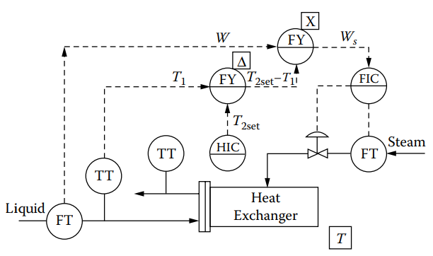
Figure 1.1d [Steam flow is calculated here to satisfy the steady-state heat balance].
Dynamic Model
Figure 1.1d illustrates how a step decrease in liquid flow in a feedforward model results in a simultaneous and proportional step decrease in steam flow. However, transient errors are expected following a change in load in feedforward control systems. Figure 1.1e shows two typical dynamic responses of the controlled variable, where the dashed curve represents an offset resulting from a 10% error in the static calculations.
If there is no static error, the temperature eventually returns to set point. However, the dynamic balance is missing because the decreased steam flow does not result in an instantaneous decrease in heat-transfer rate. This is because the temperature difference across the heat-transfer surface must first be decreased, which requires a decrease in shell pressure.
The lower shell pressure at lower loads means that the shell contains less steam as the load decreases. As the static feedforward system does not overtly lower the steam inventory in the shell, it is lowered through a lagging heat-transfer rate, resulting in a transient rise in exit temperature on a falling load, and a transient temperature drop follows a rising load. This transient error reveals a dynamic imbalance in the system, indicating that on a drop in load, the exchanger temporarily needs less heat than the steam flow controller is allowing. To correct the transient temperature error, a further cutback in the flow of energy must be applied to the exchanger beyond what is required for the steady-state balance.
Figure 1.1f provides a more general explanation, showing the load and the manipulated variable entering the process at different points and encountering different dynamic elements. In the case of the heat exchanger example, the liquid enters the tubes while the steam enters the shell, and the heat capacities of the two locations are different. As a result, the controlled variable responds more rapidly to a change in liquid flow than to a change in steam flow, and the lag time of the load input is less than that of the manipulated variable.
The objective of the feedforward system is to balance the manipulated variable against the load by providing the forward loop with compensating dynamic elements. Neglecting steady state considerations, the dynamic model must contain certain elements to balance a process having parallel first-order lags, as shown in Figure 1.1f. The lag time of the load input must be duplicated in the forward loop, and the lag time in the manipulated input of the process must be cancelled. Thus, the forward loop should contain a lead lag, with the lead time constant equal to the lag time constant of the manipulated input, and the lag time constant equal to the lag time of the load input. In the case of the heat exchanger, the temperature rise on a load decrease is caused by the fact that the lag time of the manipulated input is longer than the lag time of the load input.
This is the direction in which the load change would drive the process in the absence of control.
In transfer function form, the response of a lead-lag unit is
(11) ![]()
where ![]() is the lead time constant,
is the lead time constant, ![]() is the lag time constant, and
is the lag time constant, and ![]() is the Laplace operator.
is the Laplace operator.
The frequency response of a feedforward loop is usually not significant, since forward loops cannot oscillate. The most severe test for a forward loop is a step change in load.
The response of the lead-lag unit output ![]() to a step in its input
to a step in its input ![]() is
is
(12) ![]()
Its maximum dynamic gain (at ![]() =0) is the lead/lag ratio
=0) is the lead/lag ratio ![]() . The response curve then decays exponentially from this maximum at the rate of the lag time constant
. The response curve then decays exponentially from this maximum at the rate of the lag time constant ![]() , with 63.2% recovery reached at
, with 63.2% recovery reached at ![]() as shown in Figure 1.1g. The figure shows some deadtime compensation added to the lead-lag function—however, it is not required for the heat exchanger.
as shown in Figure 1.1g. The figure shows some deadtime compensation added to the lead-lag function—however, it is not required for the heat exchanger.
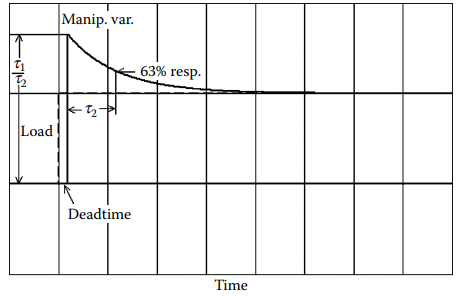
Figure 1.1g [The step response of a lead-lag unit with deadtime compensation].
When adjusted correctly, the lead-lag unit provides dynamic compensation that results in a controlled variable response similar to that in Figure 1.1h. This response is characteristic of feedforward-controlled processes. However, since most processes are not simple first-order lags, a first-order lead-lag unit cannot provide a perfect dynamic balance. Nevertheless, a significant reduction in peak deviation is achieved compared to the uncompensated response, and the area can be evenly distributed on both sides of the set point.
In Figure 1.1i, the lead-lag unit is applied to the flow signal as [![]() ]. The settings of the lead-lag unit are specific to the load input and must be placed in a location where it can modify that signal and not affect any other signals. No dynamic compensator is included for
]. The settings of the lead-lag unit are specific to the load input and must be placed in a location where it can modify that signal and not affect any other signals. No dynamic compensator is included for ![]() , as its changes are not expected to be rapid.
, as its changes are not expected to be rapid.
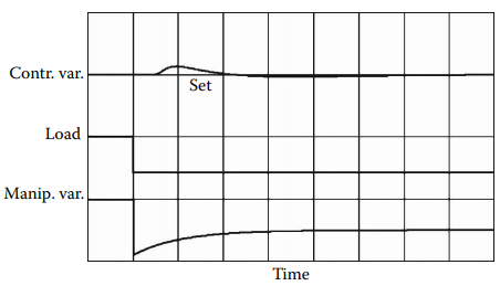
Figure 1.1h [The typical step response of a dynamically compensated feedforward system].
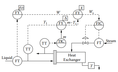
Figure 1.1i [Feedforward-feedback control of the heat exchanger, with dynamic compensation].
Tuning the Lead-Lag Unit
To begin, the lead and lag time constants should be initially set at equal values or zero to introduce a load change without dynamic compensation, so as to determine the direction of the error. If the response follows the direction the load would drive it, the lead time should exceed the lag time, otherwise, the lag time should be greater. Afterward, the time required for the controlled variable to reach its maximum or minimum value should be measured and set as the smaller time constant in the lead-lag unit.
For instance, in Figure 1.1e, the temperature response aligns with the direction the load would drive it, indicating that the lead time setting should exceed the lag time setting. The smaller time constant, equal to the time required for the temperature to rise to its peak in Figure 2.9e, should be set as the lag time setting, with the greater time constant set at twice this value. The load change should be repeated, and if the peak deviation is reduced, but the curve is still not evenly distributed around the set point, the greater time constant can be increased and the load change repeated.
Once the difference between the lead and lag settings is correct, the area of the response curve (integrated error) should be equally distributed around the set point. To achieve this, both settings can be increased or decreased while maintaining their difference constant, until the minimum error amplitude is attained. When properly tuned, the steam energy equivalent of the transient in Figure 1.1e should match the extra steam introduced in Figure 1.1g.
If there is significantly greater deadtime in the load path than in the manipulated-variable path, deadtime compensation can be added to reduce peak deviation. However, if the manipulated-variable path has the longer deadtime, exact compensation is impossible, as in the heat exchanger. Nonetheless, careful adjustment of the lead-lag compensator can still result in zero integrated error.
Adding a Feedback Loop
To eliminate any steady-state errors resulting from offset, feedback can be added by replacing the feedforward set point with a controller, as illustrated in Figure 1.1i. This creates a cascade where the feedback controller adjusts the set point of the feedforward system, which in turn adjusts the set point of the manipulated flow controller.
While the feedback controller should have the same control modes as it would without feedforward control, the settings need not be as tight. A tightly set feedback controller can alter the correct position calculated by the feedforward system, producing another disturbance that prolongs the settling time of the system. Thus, the feedback controller must have an integral mode to eliminate any steady-state offset caused by errors in the sensors, the model, or the calculations.
However, the integrated error sustained by the feedback controller following a load change is markedly reduced compared to what it would be without feedforward. Now, its output changes only an amount equal to the change in the error in the feedforward calculation. For small load changes, this change in error approaches zero, resulting in an integrated error of zero, with or without dynamic compensation.
Without dynamic compensation but with feedback, the transient in Figure 1.1e would be balanced by a following transient on the other side of the set point, prolonging the response without reducing the peak deviation. Therefore, the dynamic compensator needs to be tuned with the feedback controller in manual mode to approach zero integrated error before adding feedback.
Linear and Bilinear Feedforward Systems
The relationship shown in the energy balance of is bilinear:
(13) ![]()
steam flow is related to both liquid flow and to temperature rise in a linear manner, but as their product rather than their sum or difference. This distinction is crucial to the successful functioning of feedforward control because a bilinear system has variable gains. The feedforward gain – the ratio of steam flow to liquid flow – varies directly with the required temperature rise. This variable gain is accommodated in the system by the multiplier [![]() ].
].
If inlet temperature were to vary so slowly that it did not require feedforward compensation or if it were not measured, then feedforward from flow alone would be required. Yet the required feedforward gain—the ratio ![]() – would vary directly with
– would vary directly with ![]() . If either
. If either ![]() or
or ![]() were to change, the feedforward gain should change with it. For a bilinear process, then, a linear feedforward system having a constant gain is a misfit – it is accurate at only one combination of secondary load and set point. To be sure, feedback control can trim any errors in the feedforward calculation and return the deviation to zero.
were to change, the feedforward gain should change with it. For a bilinear process, then, a linear feedforward system having a constant gain is a misfit – it is accurate at only one combination of secondary load and set point. To be sure, feedback control can trim any errors in the feedforward calculation and return the deviation to zero.
But if the error is in the gain term, the feedback controller should adjust the feedforward gain, through a multiplier—otherwise the gain will be incorrect for all subsequent flow changes, resulting in only partial feedforward correction or even overcorrection.
Eliminating inlet temperature as a variable in Figure 1.1i also eliminates the difference block [![]() ]. The controller output m then goes directly to the multiplier, and in reducing the temperature deviation to zero, m will assume a value representing
]. The controller output m then goes directly to the multiplier, and in reducing the temperature deviation to zero, m will assume a value representing ![]() . If either
. If either ![]() or
or ![]() were then to vary, the feedback controller would respond to the resulting deviation by changing its output until the deviation returns to zero. In so doing, it has changed the gain of the multiplier to the new value of
were then to vary, the feedback controller would respond to the resulting deviation by changing its output until the deviation returns to zero. In so doing, it has changed the gain of the multiplier to the new value of ![]() .
.
Control of composition is also a bilinear process. The required ratio of two flows entering a blender, for example, is a function of their individual compositions and that of the blend. Similarly, the ratio of product flow to feed rate or steam flow to feed rate in a distillation column or evaporator also varies with feed and product compositions. In general, temperature and composition loops are bilinear, and their flow ratios should always be adjusted through a multiplier. By contrast, pressure and level loops are linear, and their feedforward gain can be constant. An example of the latter is three-element drum-level control, where each unit of steam removed from the drum must be replaced by an equal unit of feedwater – the feedforward gain is constant at 1.0.
This distinction is crucial because many “advanced” multivariable control systems are based on a linear matrix with constant coefficients. The plant is tested to develop the coefficients that relate the variables, and the control matrix is built from these results. When the plant operating conditions move away from the original test conditions, the fixed coefficients in the control matrix may no longer represent the process relationships accurately, degrading the performance of the feedforward loops. This may require frequent retesting and recalibration of the matrix. Some multivariable systems contain multiple matrices, each corresponding to its own set of operating conditions and switched into service when those conditions develop.
Self-tuning feedforward control is also available, applied either in a linear (additive) or bilinear (multiplicative) manner, as configured manually. The parameters that are tuned adaptively are the steady-state gain and a lag compensator.
The steady-state gain is adjusted to minimize integrated error following a change in measured load, and the lag is adjusted to minimize integral-square error. Load changes must be sharp, clean steps, with settling time allowed between them, for tuning to proceed effectively. But once tuned, random disturbances can be accommodated. However, self-tuning is only recommended where precise modelling and flow control are unavailable.
Performance
In a feedforward system, the use of feedback does not diminish the performance improvement achieved by the feedforward control. Prior to feedforward control, the feedback controller had to change its output to respond to all load changes. However, with feedforward control, the feedback controller only needs to adjust its output by the amount that the feedforward system fails to correct. For example, if a feedforward system can control steam flow to within 2% of the required amount, the feedback controller only needs to adjust its output to compensate for 2% of the load change, rather than the full change.
The reduction of ![]() in the equation
in the equation ![]() by a ratio of 50/1 results in a corresponding reduction in E by the same ratio. It is not uncommon to achieve a 10/1 reduction in errors resulting from load changes, and some systems have improved by a factor of 100/1.
by a ratio of 50/1 results in a corresponding reduction in E by the same ratio. It is not uncommon to achieve a 10/1 reduction in errors resulting from load changes, and some systems have improved by a factor of 100/1.
Figure 1.1j demonstrates the control performance of a steam-heated exchanger that has experienced a step decrease in process flow. Although the static feedforward model significantly reduces the peak deviation, it prolongs the settling time and does not improve the integrated error. Therefore, dynamic compensation is crucial to maximize performance. However, due to the deadtime in the path of the manipulated variable being longer than that in the load path, the lead-lag compensator cannot be perfect. Nevertheless, the compensator has been tuned to eliminate any integrated error.
The feedforward system is typically more expensive and requires more engineering effort than a feedback system. Therefore, before implementing feedforward control, it is essential to determine whether the control improvement it brings justifies the extra cost and effort. Feedforward control is most frequently applied to processes that are highly sensitive to disturbances and slow to respond to corrective action, as well as product streams that are relatively high in value. Distillation columns with 50 or more trays are the primary systems controlled using feedforward technology. Other challenging processes, including boilers, multiple effect evaporators, direct-fired heaters, waste neutralization plants, solids dryers, and compressors, have also benefited from feedforward control.
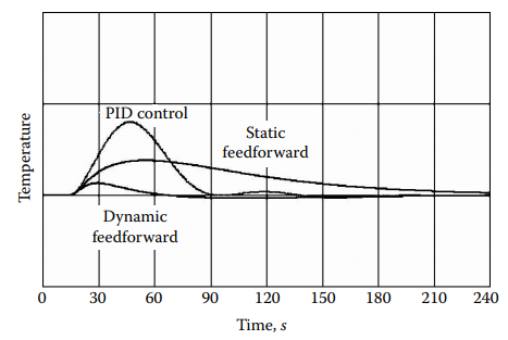
Figure 1.1j [Comparison of feedforward control of a heat exchanger against optimally tuned PID feedback control].
Variable Parameters
Heat exchangers have dynamics and gain that vary with flow, making it difficult to optimize the settings of both the PID controller and the feedforward compensator for different flows. To compensate for gain variations when using PID control alone, an equal-percentage steam valve can be used, whose gain varies in direct proportion to steam flow. However, when combined with bilinear feedforward, the output of the PID controller goes through a multiplier that maintains a constant loop gain while manipulating steam flow linearly.
Differentiation of the heat-balance equation, the process gain to vary inversely with process flow W:
(14) ![]()
In heat-exchanger systems, deadtime and lags vary inversely with process flow, which can lead to instability at extreme flow rates. To prevent this, the PID controller’s integral time must be set relative to the slowest response, and the derivative time must be set relative to the fastest response. Ideally, the lead and lag settings of the feedforward dynamic compensator should also be programmed as a function of measured flow to minimize peak deviation following a load change.
Self-tuning feedforward compensators and feedback controllers can accommodate parameter variations, but they are less accurate in arriving at optimal settings and always late, tuning for the previous flow condition rather than the next one.