It is important to have a complete understanding of the phenomenon of interaction and decoupling, as the methods discussed in this section may not be applicable in all cases. Having knowledge of alternative options for overcoming interactions between control loops can be beneficial.
Multiloop Systems
When multiple control loops are involved in controlling a unit process, it is not possible to determine how one loop may impact another through a magic formula alone. It requires a thorough understanding of the process. If one loop directly influences another, oscillation in the first loop may cause oscillation in the second and even downstream loops. For instance, if the same pump feeds two flow loops, oscillation in one loop can trigger oscillation in the second loop.
When a loop is cycling, it is crucial to identify the cause of the cycling. It could be the process itself, or other loops or even the loop in question. One way to investigate the cause is to switch the specific loop to manual mode. If the cycling continues, it is likely that an external factor is causing the cycling.
Another issue that can arise is hidden cycling, which occurs when a cycle is present but is concealed by noise. To detect a hidden cycle, readings should be collected in manual mode, and power spectral density analysis should be performed on the collected data. In such cases, hidden cycles will appear as peaks.
In some setups, the loops must respond at the same speed. The tools available to assess loop health and performance are essential in either case.
Control Loop Analysis
The following criteria should be met for a control system to perform in an optimal manner:
- The power spectral density should be flat, no cycling present.
- Cumulative power spectral density should be continuous.
- Statistical analysis: Data distribution should be a bell curve, variability should be small, valve movements should be minimized.
- Development of a process model is desirable to validate the process and to find tuning parameters.
- Robustness analysis is recommended to validate tuning parameters.
- The process should be analyzed to check for hysteresis and backlash, stiction, noise, process model inaccuracy, hidden cycling, and nonlinearities.
- Oscillation should be evaluated by determining the area under the curve, which is a good indicator of control quality.
- Cross-correlation and multivariate techniques can be used to measure interaction between signals and loops. They can also help to determine whether multivariable control should be considered.
- Performance indexes, such as variability, IAE, and Harris index, should all be monitored.
Interacting Loops
Figure 14.1 depicts an example of a control system with multiple loops that may interact. In this system, two liquids are mixed, with one being the expensive process fluid controlled by flow controller 1 (FC1) at a rate of 100 GPM, while the other, water, is added by flow controller 2 (FC2) to dilute the process fluid, maintaining a total flow rate between 200 and 400 GPM.
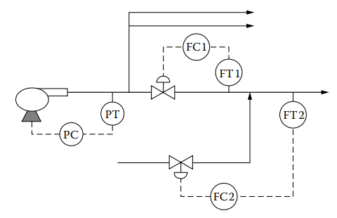
Figure 14.1 [Illustration of potentially interacting control loops].
All three loops in this system have the potential to be fast, with a response time of less than 30 seconds achievable. However, it is important that the loops have different speeds, as if they do not, an upset in one loop can cause oscillation and upset the other loops. The decision of which loop should be the fastest depends on the process itself and which controlled variable needs to remain constant for the other loop(s) to function correctly.
In this example, observing the process indicates that for FC1 to function properly, the upstream pressure to its control valve must remain constant. Therefore, the pressure loop must be faster than flow loop 1. If the pressure and flow loops were tuned to have the same speed of response, they may initially work, but eventually, a disturbance could cause the loops to oscillate.
For instance, if another valve suddenly closes, causing an increase in line pressure, and the pressure control loop is not faster than the flow loop, the flow through FC1 will increase. To correct the flow increase, FC1 will close its valve, causing the pressure to rise. Eventually, the pressure loop will slow down the pump, leading to a decrease in flow. As the flow drops, FC1 will open its valve to compensate, which will cause the pressure to decrease, and the pressure control (PC) will speed up the pump, causing the flow to increase again. If the PC is not faster than FC1, this cycle will repeat, and the two loops will oscillate and potentially resonate.
Similarly, since FC1 controls the process fluid feed to the flow loop controlled by FC2, flow loop 1 must be faster than flow loop 2. Otherwise, a disturbance in flow 1 could cause both flow controllers to react, resulting in oscillation.
Tuning to Eliminate the Interaction
If PC is not faster than FC1, steps 3, 4, 5, and 6 will continuously repeat, causing the two loops to oscillate and potentially resonate. Similarly, to avoid oscillation, flow loop 1 must be faster than flow loop 2 since FC1 controls the process fluid feed to the flow loop controlled by FC2. When loops interact, it is important to ensure that their response speeds are significantly different to avoid potential oscillation. It is recommended to select response speeds that differ by a factor of three to five, and for highly interactive loops, a speed ratio of up to 10:1 may be required to fully decouple them.
For the control system described in Figure 14.1, this means that the response time of the pressure loop determines the response time of flow loop #1, and the response time of flow loop #1 determines the response time of flow loop #2. To tune interacting loops, one would place the downstream loop in manual while tuning the upstream loop, and once the upstream loop’s speed of response is determined, use a multiple of that to set the downstream controller.
To tune the control system in Figure 14.1, one would place FC1 and FC2 in manual mode while aggressively tuning the pressure controller to provide a high speed of response. Once the pressure controller is tuned, it is placed in automatic mode, and FC1 is then tuned for a response time that is at least three times slower than the pressure loop response time, ideally 5 to 10 times slower. Once FC1 is tuned, both the pressure controller and FC1 are left in automatic mode while FC2 is being tuned for a response time which is at least three times slower than flow loop FC1, ideally 5 to 10 times slower.
The tuning of the three interacting loops can be summarized in three steps:
Step 1: Tune PC for quick response while other loops are in manual mode (Figure 14.2).
Step 2: Tune FC1 for moderate response while PC remains in automatic mode and FC2 in manual mode (Figure 14.3).
Step 3: Tune FC2 for a slow response while PC and FC1 both remain in automatic mode (Figure 14.4).
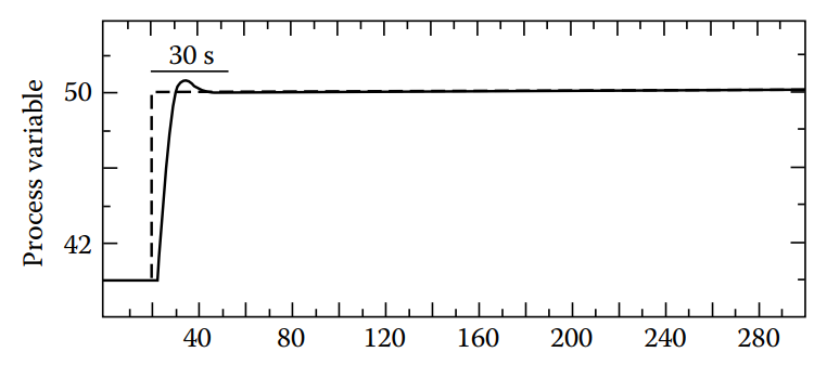
Figure 14.2 [After the fastest loop is tuned, measuring its response time (settling time), which in this case is 30 seconds].
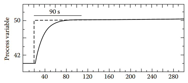
Figure 14.3 [Tuning the less fast loop for a response time (settling time) that is three times that of the fastest loop or in this case is 90 seconds].
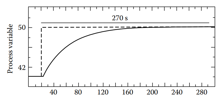
Figure 14.4 [Tuning the least fast loop for a response time (settling time), which is three times that of the less fast loop or in this case is 270 seconds].
Reducing the speed of response to remove interaction has the disadvantage of causing control loops to become sluggish and unable to effectively correct upsets and disturbances. More sophisticated techniques of decoupling may be required in such cases. In a cascade system, the inner loop should be faster than the outer loop to avoid oscillation. A summary of the steps required to tune any number of interacting loops can be found in Table 14.1.
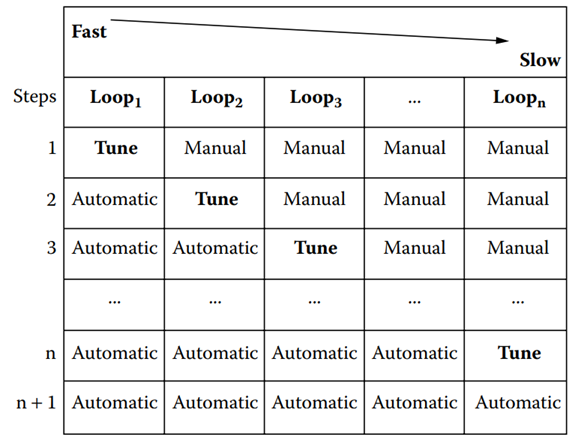
Table 14.1 [The sequence of steps to be used in tuning any number of interacting control loops].
Synchronising Loops
In certain control systems, the loops work together without interacting, and are referred to as synchronized loops. It is important for these loops to have the same response time, without any physical link between them that could cause interaction.
An example of synchronized loops is found in batch mixing systems. Figure 14.5 shows a control system for mixing three ingredients in a mix tank. The aim of the system is to maintain the required ratio of ingredients, even during startup or shutdown, or when the production rate changes.
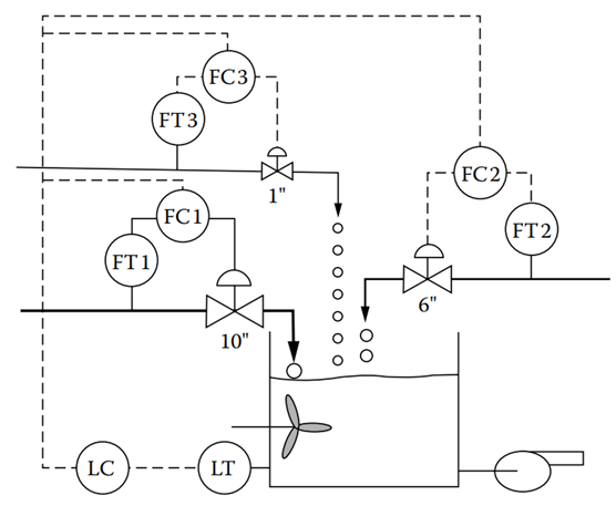
Figure 14.5 [In order to keep the ratio of ingredients constant during load changes, the loops have to be synchronized (their speed of response has to be the same].
As the control valves and pipe volumes associated with the three flow control loops are substantially different, it is likely that their process gains, dead times, and time constants also differ. If all three loops were tuned for 10% overshoot (or any other criterion), the response times of the loops would not be the same. This would result in the recipe flow ratios being out of balance until all three flows reach their new set points and regain stability.
To ensure that all three loops move at the same speed, one should determine the response time of the slowest loop and match the response times of the others to it. Normally, the slowest loop is the one with the largest dead time. The steps involved in tuning synchronizing loops are:
- Apply an upset (bump test) to each loop. This can be a temporary change of set point.
- Determine which loop is the slowest from the responses of the loops.
- Tune the slowest loop for maximum speed of response and measure the response time that results.
- Adjust the tuning parameters of the other loops so that they will also have approximately the same response time.
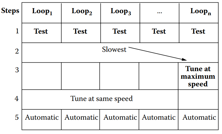
Table 14.2 [Summary of steps required in tuning to synchronize control loops].
When tuning loops that need to work in harmony, it is important to select tuning parameters that give similar response times. This can be done using software where the expected speed can be specified. If done by hand, techniques such as pole placement, Internal Model Control, or Lambda tuning should be used.