The block diagram provides a convenient method for deriving a set of state equations for a system that is specified in terms of a single input/output differential equation. A set of ![]() state variables can be identified as the outputs of integrators in the diagram, and state equations can be written from the conditions at the inputs to the integrator blocks (the derivative of the state variables). There are many methods for doing this; we present here one convenient state equation formulation that is widely used in control system theory.
state variables can be identified as the outputs of integrators in the diagram, and state equations can be written from the conditions at the inputs to the integrator blocks (the derivative of the state variables). There are many methods for doing this; we present here one convenient state equation formulation that is widely used in control system theory.
Let the differential equation representing the system be of order ![]() , and without loss of generality assume that the order of the polynomial operators on both sides is the same:
, and without loss of generality assume that the order of the polynomial operators on both sides is the same:
(1) ![]()
We may multiply both sides of the equation by ![]() to ensure that all differential operators have been eliminated:
to ensure that all differential operators have been eliminated:
(2) ![]()
from which the output may be specified in terms of a transfer function. If we define a dummy variable ![]() , and split Eq. (2) into two parts
, and split Eq. (2) into two parts
(3) ![]()
(4) ![]()
Eq. (3) may be solved for ![]() ,
,
(5) ![]()
and rearranged to generate a feedback structure that can be used as the basis for a block diagram:
(6) ![]()
The dummy variable ![]() is specified in terms of the system input u(t) and a weighted sum of successive integrations of itself. Figure 1.1 shows the overall structure of this direct-form block diagram. A string of n cascaded integrator (
is specified in terms of the system input u(t) and a weighted sum of successive integrations of itself. Figure 1.1 shows the overall structure of this direct-form block diagram. A string of n cascaded integrator (![]() ) blocks, with
) blocks, with ![]() defined at the input to the first block, is used to generate the feedback terms,
defined at the input to the first block, is used to generate the feedback terms, ![]() , in Eq. (6).
, in Eq. (6).
Eq. (4) serves to combine the outputs from the integrators into the output ![]() .
.

Figure 1.1 [Block diagram of a system represented by a classical differential equation].
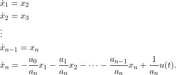
A set of state equations may be found from the block diagram by assigning the state variables ![]() to the outputs of the n integrators. Because of the direct cascade connection of the integrators, the state equations take a very simple form. By inspection:
to the outputs of the n integrators. Because of the direct cascade connection of the integrators, the state equations take a very simple form. By inspection:
(7) 
In matrix form these equations are
(8) 
The ![]() matrix has a very distinctive form. Each row, except the bottom one, is filled of zeroes except for a one in the position just above the leading diagonal. Eq. (8) is a common form of the state equations, used in control system theory and known as the phase variable or companion form. This form leads to a set of state variables which may not correspond to any physical variables within the system.
matrix has a very distinctive form. Each row, except the bottom one, is filled of zeroes except for a one in the position just above the leading diagonal. Eq. (8) is a common form of the state equations, used in control system theory and known as the phase variable or companion form. This form leads to a set of state variables which may not correspond to any physical variables within the system.
The corresponding output relationship is specified by Eq. (4) by noting that ![]() .
.
(9) ![]()
But ![]() , which is found from the
, which is found from the ![]() th state equation in Eq. (7). When substituted into Eq. (9) the output equation is:
th state equation in Eq. (7). When substituted into Eq. (9) the output equation is:
(10) 
![]()
Example
Draw a direct form realization of a block diagram, and write the state equations in phase variable form, for a system with the differential equation.
(11) ![]()
Solution: The system order is 3, and using the structure shown in Fig. 1.1 the block diagram is as shown in Fig. 1.2.
The state and output equations are found directly from Eqs. (8) and (10):
(12) 
(13) 

Figure 1.2 [Block diagram of the transfer operator of a third-order system found by a direct realization].
![]()